Henry 2K Classic
Modifications / Corrections / Upgrades
By: NE7X
06/23/2011
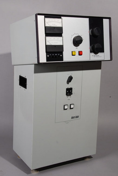
I acquired a practically working pristine Henry 2K Classic HF RF amplifier. The person who I purchased the amplifier from told me one of the 3-500Z tubes shorted resulting in opening the bias zener. He replaced both tubes and the bias zener, however the amplifier was not functioning properly.
- The amplifier was putting 1KW output, however the 3-500Z tubes were running extremely RED HOT during idle (key/no drive).
- When the amplifier was keyed with >30 watts RF drive, the Ig grid meter pegged full scale.
A correct working amplifier using a pair of 3-500Z tubes in grounded-grid configuration, keyed, no drive, the tubes should only show a slight pink color and the meters should read:
Ip meter = +/- 100ma plate current
Ig meter = 0ma grid current.
After I got the amplifier home and on the workbench, I started troubleshooting the issues.
The first thing I did was to validated the bias circuit and zener diode wiring to the factory schematic. I wanted to make sure the guy who I purchased the amplifier from did not make any mistakes when he replaced the zener. All wiring matched the factory schematic perfect.
Next I started tracing wires in the metering circuit and I noticed the wiring did not match the factory schematic. It was oblivious by the appearance of the solder connections that someone previously change components and wiring in the metering circuits.
Not having any idea what or why these wiring changes were made, I completely disassembled the meter circuit wiring, then rewired it back 100% to the factory schematic wiring diagram, including all part values. My thought was if I rewire everything back to the factory schematic, it should eliminate all the wiring guess work and put everything back to factory original.
However once I finished rewiring the metering circuit, I discovered I made "negative" progress, because now the Ip plate meter was also pegging full scale. At this point in time, no matter what part I checked or replaced, or what wire I confirmed was correct per the factory schematic, I just could not resolve any of these issues.
I posted a message on the http://qrz.com RF Amplifier Forum, listing the problems I was having and immediately started receiving responds from individuals to try this and check that. Even thou I was corroborating and troubleshooting the issues with total strangers, there was this "Band-of-Brothers" among everyone on the forum with an eagerness and willingness to help me resolve these issues.

Henry 2K Classic under repair
Here is a the original metering schematic from page 24 of the factory manual

Full Henry 2K Classic Factory Manual
FIX:
After several days of QRZ forum exchanges, Tom W8JI discovered the following errors in the factory schematic wiring diagram:
Factory Schematic Errors:
- D1 bias zener is shown "cathode to F1" and "anode to R1." This is incorrect and wired BACKWARDS! The correct wiring is "cathode to R1" and "anode to F1" (page 22 of factory manual)
- The T/R relay contacts are shown in "transmit" mode, while the relay is shown in an "un-energized" state (page 22 of factory manual)
- In the parts list metering resistor R115 is listed as .2 ohms and should be 150 ohm (page 34 factory manual)
- In the parts list metering resistor R119 is listed as 150 ohms and should be .2 ohms (page 34 of factory manual)
After re-wiring the bias and metering circuits with the above corrections, the tubes were no longer running red hot on idle, and the meters were no longer pegging full scale with >30 watts drive. Having the bias zener wired in backwards caused the tubes to idle hard above cutoff, and having the wrong meter shunt resistors caused the meters to peg full scale.
Metering Circuit Modification:
W8JI stated the Henry metering circuit was a poor design and recommended that I perform the following modification upgrade to the metering circuit, which I did.
- Remove R106, R119 & D107
- Replace C114 with .1uf
- Replace R115 with 150 ohm
- Connect C114 & D106 direct to B- rail
- Connect junction of R115/R116 direct to B- rail thou F101
- Add four 10 ohm 10 watts 175P pulse resistors in series with B+ HV to RF deck J102 for current limiting.
Here is the schematic for the metering modification

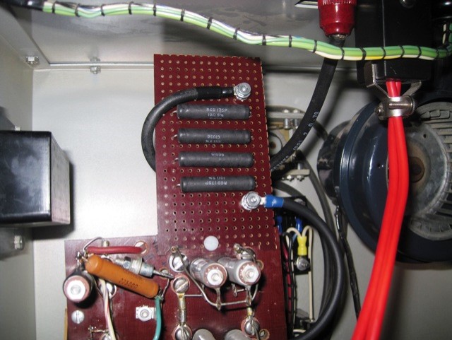
Four 10 ohm (40 ohms total) HV Pulse Current Limit Resistors in series with the HV B+ line feeding J102 top RF deck. One 10 ohm resistor for every 1000V of the HV supply. They provide HV pulse current limiting if a voltage surge occurred on the B+ HV line due to a tube shorting or filter cap going. Highly recommend you add these resistors to any RF amplifier's HV supply.
RCD Part Number: 175P-10R0-FBW
Ameritron Part number: 110-1100-1
Description: RESISTOR, 10 Ohm 10 Watt, 175P, 10%
P = Pulse Current Limit Option
Conclusion:
I now have the Henry 2K Classic fully operational and working perfectly. The 3-500Z tubes are running a nice soft rose pink color and both the Ip and Ig meters are running in the proper ranges.
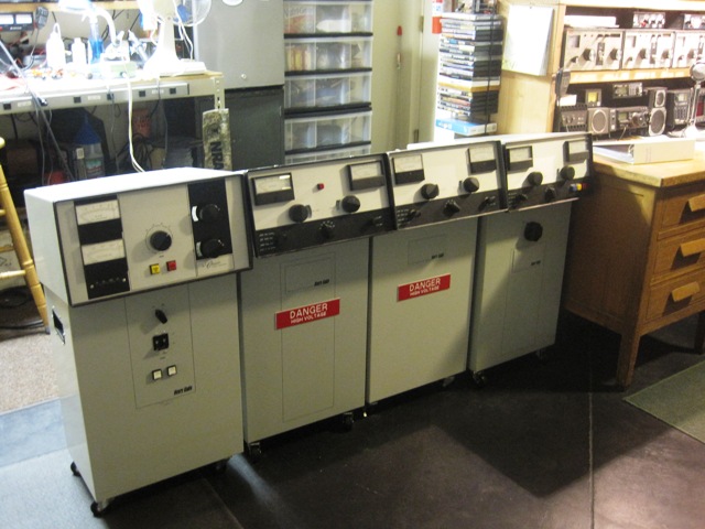
Here is a picture of the Henry 2K Classic (Left) in its operating position alongside his two 2K-4 brothers (center) and 3K-A sister (right).
A special thanks for everyone on the http://qrz.com RF Amplifier forum. Without everyones help and input, I may not of gotten this amplifier working.
Recognize: W8JI, W1QJ, AF6LJ, W9GB, K9FV, K9ASE and others for their collective thoughts, ideas, suggestions and positive attitudes.
Henry RF Amplifier Information Center Web Site
Additional Information about other Henry RF Amplifiers
Modifications & Upgrades
Happy DXing
Return to NE7X web site