*** DANGER ***
RF Amplifiers Have Lethal HIGH VOLTAGE Inside
I acquired a Henry 2K in pristine condition, however when first powered up I could not get an Ip (Plate Current) dip. Everything appeared to be working, HV was good, blower fan was strong, both 3-400Z were lit and appeared healthy. However when keying the amplifier with 30 watts drive, Ip was about 300ma and there was only about 200 watts RF output, no Ip dip.
Troubleshooting:
Checking the following components: HV RFC, TUNE air-variable, door knob capacitors, tank coil and 3-400Z tubes, everything checked good. The only thing left was the band selector switches. Visually looking over the band selector switches, they all looked good, no burn spot or bent contacts.
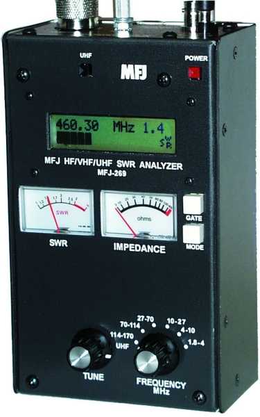
Jim N6MJD suggested that I disconnect the AC power from the amplifier, then connect my MFJ-259B Antenna Analyzer to the amplifier's RF output SO-239 connector. I can then either leave the 3-400Z tubes installed, or remove the tubes and use a 3.3Kohm resistor clip-lead from Plate connections to chassis ground (see picture below). This is required to provide enough capacitive resistance to the circuit.
Mechanically place T/R RY3 relay in transmit position and place the band selector to desired band. Tune the MJF-259B to the Mid Band Freq output of the desired band and begin to try and tune the output tank Circuits (Plate Tune and Load on the AMP) for proper SWR 50 Ohm SWR 1.1 (resonance). You should have the same results like when trying to acquire Ip dip when the amplifier was turned on with drive. The MFJ-259B is a much safer way to troubleshoot the issue.
Issue Identified:
What I found, the 5 wiper contacts all needed to make good connection all the time. If pin 1 is selecting the desired Coil Tap, then Contacts 2 thru 4 need to short the remaining coils as it will affect tuning if they do not make a good connection.
All four wafer switches MUST track together, so when 20 meters is selected, all four wafer switches are in the 20 meter position. After further investigation of the band wafer switches, the band selector switch S3/S4 was not registered correctly, it was off by one contact point. When 10 meters was selected for example, the lower S4 wiper was correct and the upper S3 wiper was sitting on 15 Meters. Also, some of the wafer wiper contacts were not making contact on the unused coils causing tuning issues as well.
Once the switches were aligned, using the MFJ-259B was a really nice way to test Band Switch s3/s4 and it was great to see the Bands Tune. This again is testing the output tuning area s3/s4. See the below picture of the big coils and the bottom side is s4.
The band selector is composed of four separate wafer switches, two for RF input and two for the RF output. The two wafer switches for the RF input select both sides (in/out) of the tuned input coils. The two wafer switches for the RF output select the two different high and low band RF tank coils. All four of the wafer switches are ganged/connect-together using pulleys, cables, drive shafts and a 90 deg gear assembly. See the following picture.


 2DK-5 and 2K-Classic