by Richard L. Measures, AG6K, April 1988
WHY?
If you have ever tried to use the 80 meter phone band for local communications on winter evenings, you probably experienced situations where under 200Km propagation was almost nonexistent.
The group of friends that I talk with on 80 meters was plagued by these "winter doldrum" conditions so a few of us put up 160 meter antennas to see if the situation could be improved. We discovered that, when the 80 meter band was essentially useless for short-haul propagation, the 160 meter band provided good communication.
There were tradeoffs to using the 160 meter band: Most of us had to put up compromise antennas that would fit on a city lot -- like the end-fed Marconi . These antennas were not as efficient as full-size dipoles. The only practical way to compensate for the lack of efficiency was to increase power. Another problem with 160 meters was a peculiar type of fading that would take a 100 watt signal down into the sky-noise for 10 to 20 seconds every couple of minutes. Again, the solution was to increase power.
Most HF amplifiers that were manufactured in the last twenty years did not include 160 meters because high power was permitted there only during the nearly useless daylight hours. The easiest but not the most cost effective or educational way of increasing power on 160 meters is: sell the old 80 through 10 meter amplifier and purchase a new model that has 160 meters included. I chose to convert my old SB-220 to include 160 meters and pocket the knowledge and experience plus the roughly 600 dollar difference.
After converting my own amplifier, I have been involved in modifying six other amplifiers. 160 meters can be added to almost any similar amplifier by using the same basic principles.
What follows is the theory, practice and pitfalls or "gotchas" of this modification.
HOW
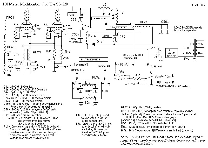
To make an 80 meter circuit work on 160 meters, the capacitances and the inductances must be doubled. This includes the components in the output and input resonant circuits as well as the bypass capacitors and the anode RF-choke but usually not the filament-choke as will be explained later. The added bypass capacitors and the added anode RF-choke can be left in the circuit for operation on the other bands, but the 160 meter tuned-circuit components must be switched into the circuit for use on 160 meters only and switched out of the circuit for operation on the other bands. . .
If extra bandswitch contacts [75m/80m] had been provided by the manufacturer [like on the Henry Radio Company's 2K-4 and 3KA models] , the job of switching would be simpler. Therefore the switching must be done with relays controlled by a two position toggle-switch [S1a]. One switch position is used for 80 through 10 meters and the other switch position is for 160 meters only, with the main bandswitch set to the 80 meter position.
COMPONENT RATINGS:
The ratings of the components that are used in this project deserves special attention because we are dealing with surprisingly high RF-currents and RF-voltages. The RF circulating-current in a tank-circuit is much higher than the indicated anode-current [in this case,.8a] might imply.
CAPACITOR CURRENT-RATINGS:
The capacitors used must not only be rated for voltage, they must also be rated for the substantial RF currents encountered. For example, just because a 500pF "TV doorknob" capacitor is rated at 20,000VDC does not mean that it could handle even 530vRMS at 1.8MHz. At 1.8MHz, the reactance of 500pF is minus j176.7ohm. The {apparent} current through the capacitor is: 530v/176.7ohms = 3 amperes which would cause severe heating, a rapid change in capacitance and a meltdown in this type of capacitor.
Special capacitors that are made to handle RF current are required for this project. Some examples of RF current-rated types of capacitors are the transmitting mica, ceramic, transmitting "doorknob" and air or vacuum-dielectric capacitors.
The RF [circulating or flywheel] current in the tank-circuit of an amplifier is roughly equal to "Q" multiplied by the DC anode-current. In this case, the circulating current is [Q=12] x [.8A] c.10a. The tuning capacitor and the loading capacitor must be able to withstand this substantial RF-current. When the tuning capacitor's padder is switched into the circuit on 160 meters and the tuning capacitor is set to minimum capacity, the padder capacitor must be able to withstand more than c.90% of the RF circulating current.
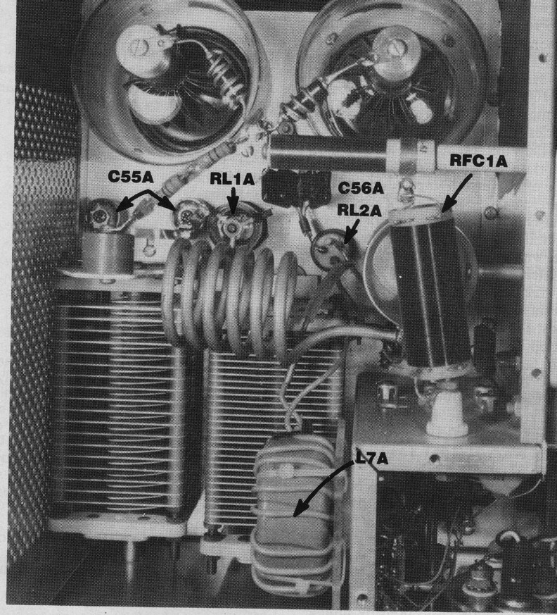
The 300pF tuning-capacitor padder [C55a] is three 100pf, 5KV or two 150pF, 5KV ceramic transmitting capacitors in parallel. The 100pF capacitors are rated at 3.4 amperes each at 1MHz.
Note: Just because a transmitting ceramic capacitor is designed to handle RF-current does not guarantee that it will work in a tank-circuit. For example, a 500pF, 5KV "Series 58 Centralab™ {now Jennings™ "Series 58"} capacitor is RF-current rated but it is rated to handle only 1.1 amperes at 1MHz and 2.5 amperes at 10MHz. The rating at 1.8MHz would probably be around 1.5 amperes. This capacitor would be unsuitable for either the tuning capacitor padder [assuming that a 500pF size was needed] or the loading capacitor padder in this project. Even the 1000pF capacitor from the same series of capacitors would be unsuitable for the loading capacitor padder [C56a] since its current rating is only 1.4a at 1MHz.
RELAYS: The current and voltage ratings of the open-contacts in the output switching relays, RL1a and RL2a, deserves special consideration because RF voltage is much more capable of jumping across open switch contacts than voltage with a frequency of 60Hz. Breakdown voltage is inversely proportional to the frequency of the voltage. At 30MHz, the breakdown voltage is roughly half of the 60Hz value.
CONDUCTOR RATINGS: RF current travels on the surface of conductors and ignores the substantial path for current below the conductor's skin. This "skin-effect" means that the current is concentrated near the surface of an RF conductor so the current density there is much higher than it would be with DC or 60Hz current. The skin-effect becomes more pronounced as frequency increases. The increased current density with RF causes exponentially [current squared times resistance] more heating at the surface of the conductor and the current rating of wire and contacts must be proportionally derated as frequency increases. For example, #12 copper wire is normally rated for 20a at 60Hz but the 30MHz rating for continuous current in #12 copper wire is only c.5 amperes.
Relays that have RF current ratings are normally derated to about 20 to 30% of the DC or 60Hz ampere rating for use at 30MHz.
Unlike RF voltage breakdown ratings, for intermittent applications like CW and SSB, the RF current ratings of wire and relay contacts may be increased; the only tradeoff being a slight decrease in overall efficiency.
VOLTAGE RATINGS: The maximum RF peak voltage that is encountered by the tuning capacitor in a properly tuned, 3-500Z, grounded-grid amplifier is approximately equal to the anode supply voltage minus about 200v. This would be about 2700v minus 200v c. 2500V peak for the SB-220.
Note: The reason for this is that when the peak anode-current is maximum and the instantaneous anode-voltage is minimum, the anode must always be about 200 volts more positive than the [grounded] grid in order to attract most of the electrons that are emitted by the cathode. If the amplifier is adjusted for too-light loading, which causes the instantaneous, minimum, anode-voltage to dip below the c.+200v level, too many electrons will flow into the grid instead of into the anode. This causes excessive grid-current and, because those electrons never make it to the plate, results in amplifier non-linearity which is euphemism for rotten-splatter.
2500v is not difficult to switch at 60Hz. But at 29MHz it is not so easy. For example: If a relay with a 3000v peak/60Hz rating were used to switch the padder-capacitor across the tuning-capacitor [RL1a], its open contacts would arc- over during operation on the higher frequency bands. This means that a special relay that has an RF voltage rating must be used. The only practical relay for this difficult job is a vacuum-relay that is [open-contact] rated for at least 2500v peak at 30MHz. A suitable relay is the Jennings™ RD 5 or RB 1 or a Kilovac™ H-8. There are many other vacuum-relays to choose from that are rated at „2500v peak at 30Mhz. Those that I listed are more common at swap meets.
The SPDT relay, RL2a, at the low voltage, 50ohm end of the tank-circuit switches the added loading-capacitor padder and the added 9micro H, tank-inductor padder. The maximum RF voltage that is encountered at these points is less than 1200v peak. An ordinary 15a open-frame relay may be used if the open contact air-gap is above average and it will withstand >4500VDC on a breakdown voltage tester. Another Jennings™ RB1 or a Jennings™ RJ1A [like the one seen in the photograph] or a Kilovac™ H-8 would be even better.
POWERING THE RELAYS
The rated coil current for an RB1 is 100mA. If speed of relay closure is not a factor, as in this application, a lower actuating current may be used. The actual pull-in current for a RB1 is about 50mA. For reliable operation and maximum coil life, a coil current of c.70mA is appropriate.
The stock, half-wave rectified, +110V relay power supply in the SB-220 is adequate for the original current load of about 25mA. The extra current load that the 160 meter switching relays place on this supply can be accommodated by changing the rectifier circuit from the stock single-diode half-wave to a four-diode full-wave-bridge rectifier circuit. This involves removing the half-wave rectifier [D16] and replacing it with a c.1a,„200piv full-wave bridge rectifier unit. The previously grounded side of the transformer winding {red wire} must be lifted above ground and connected to the input of the new rectifier unit. See the schematic diagram.
One DPDT Jennings® RB 3 can do the jobs of RL1a and RL2a, but the RB3's rated coil current of 200mA {140mA} is probably too much for the SB-220's internal +110V power supply so an extra 18 to 24 volt power supply would be required.
FILAMENT CHOKE
Most articles that have been written about 160 meter amplifier modification mistakenly presume that it is necessary to throw away the stock 80 meter to 10 meter filament RF-choke and replace it with a more inductive choke.
The SB-220 has a 9micro H filament choke. The reactance of this choke at 1.9MHz is about plus j107ohm. If a capacitor whose reactance at 1.9MHz was minus j107ohm [800pF] was connected in parallel with the 9micro H choke, the circuit would resonate and look like the needed high impedance at 1.9MHz , the original choke would do the job.
The off-frequency impedance, at the 160 meter band edges, of this resonant filament-choke circuit deserves evaluation: The admittance, Y, of a 9micro H inductor in parallel with a 800pF capacitor calculates to be Yc.1/900S [siemens {previously called "mhos"}] at 1.8MHz and 2MHz. This admittance is equivalent to an impedance of Zc.900ohm which will make little difference to the RF-paralleled cathode-circuit of the 3-500Zs, whose [averaged over 360 degrees] impedance is about 65ohms.
The extra 800pF is added to the capacitance of the output capacitor in the 160 meter, pi-network tuned-input circuit so that it is automatically switched in only on 160 meters.
TUNED-INPUT CIRCUIT
Before the values of the components in the 160 meter band pi-network, tuned-input circuit can be calculated, a value of "Q" must be chosen. "Q" is defined as the input resistance of the pi-network divided by the reactance in ohms of the input capacitor, or: Q=Rin/Xcin. If the "Q" is too low, the bandwidth of the tuned-input will be good but the minimum attainable SWR will not be especially good anywhere on the band. If the "Q" of the input circuit is too high, the SWR at the middle of the band will be good but the SWR at the band edges will not be good. So a compromise "Q" is chosen to balance bandwidth against minimum attainable SWR. According to Eimac™, in their book Care And Feeding Of Power Grid Tubes, an input-circuit "Q" of c.2 should be used. The stock SB-220 uses a "Q" of only c.1 for the 80 meter through 10 meter tuned-input circuits. This results in an SWR that is acceptable for vacuum-tube output transceivers, but less than optimum for modern all-solid-state transceivers.
Using the formulas in Eimac's book and a "Q" of 1.6, the input capacitor, C1a c.2700pF, the inductor, L1a, is between 4micro H and 5micro H and the output capacitor, C2a c.2500pF plus the extra 800pF [total c. 3300pF] needed to cancel the reactance of the 9micro H filament choke. These capacitors must be rated at „500V with a mica dielectric. The inductor, L1a, should be wound from no smaller than 24 gauge insulated copper wire or the input SWR will be degraded. If the inductor is slug-tunable, it partially facilitates adjusting the input SWR.
ADJUSTING INPUT SWR: The impedance transformation of a pi-network can not be altered by adjusting only one of the three reactive components. The impedance transformation can be altered only by adjusting two or more components.
The 160 meter pi-network's input capacitor, C1a, is not adjusted because to do so would change the design "Q" of the circuit. Adjusting the inductance will change only the center-frequency and may not result in an acceptable minimum SWR. If this is the case, C2a should be adjusted as well as L1a until the proper impedance transformation ratio and minimum SWR is achieved.
ANODE-CHOKE
Designing an anode-choke to supply the HV to the anode of an amplifier-tube would be easy if the amplifier were to be used on only one frequency. If this were the case, the unavoidable, internal self-resonant frequencies of the choke could be "parked" elsewhere by adjusting the number of turns of wire and there would be no problem.
When an amplifier is to be operated over a wide frequency range, the design of the choke is complicated. The problem is this: Enough inductance must be provided so that, at the lowest operating frequency, there will be enough inductive reactance to limit the RF current that flows through the choke and the HV-to-ground RF-bypass capacitor [C7]. The solution sounds simple, just add more turns to make more inductive reactance to reduce the RF-current that flows through the choke. The complication is this: adding turns also increases the choke's distributed capacitance which increases the number of choke self-resonances below 30MHz. If one of these self-resonances falls on an operating frequency, an unpleasant choke-fire will result and the choke will be crispy-crittered.
One traditional non-solution to the problem of adding more turns was to allow an open space of c.2cm on the coil form between the added turns and the main winding. This was supposed to decouple the inductors and avoid the self-resonance problem. This solution looks good on paper but unfortunately, as can be easily confirmed by measuring the self-resonances with a dip-meter, same-axis coil sections that are placed end-to-end couple optimally to each other and the spacing must be increased far beyond any practical limit to achieve the desired results.
The best way to prevent inductive coupling between two or more inductors is to place the inductors at right-angles to each other.
The stock anode-choke, RFC1, in the SB-220 has 50micro H of inductance. This value was chosen wisely because the lowest self-resonant frequency with this amount of inductance is above 40MHz, which is safely above the operating frequency range of the amplifier. The reactance of this choke at 1.8MHz is +j565ohm. The AC anode-voltage in the SB-220 c. 2500v peak/ˆ2 c. 1768vRMS, so the RF current through this choke would be 1768v/565ohm = 3.13a! This substantial current would cause severe heating of the #28 gauge wire in the choke and the HV bypass capacitor at the bottom of the choke so another choke is added in series with, and at a right-angle to, the original choke. The inductance of this choke [RFC1a] can be as little 65micro H or as much as 135micro H.
A 65micro H choke can be made by filling c.51mm of winding space on a 16mm diameter coil form with .36mm diameter [#27AWG] high-temperature enameled copper wire . This choke's lowest self-resonant frequency is c.35MHz so it will work well below 30MHz and also provide enough total inductance [115micro H] to avoid choke and bypass capacitor overheating at 1.8MHz. {NOTE: To avoid a meltdown, the coil form/insulating tube should not be made from PVC, nylon, or any other material that has a high RF-dissipation [D] factor. Delrin™ has an intermediate D factor. Polyethylene, TFE [Teflon], and ABS [acrylonitrile butadiene styrene] or other styrenes have low D factors. Thin-wall (c..5mm) G10 or G11 fiberglass tubing is excellent for this application because it is light weight, RF and heat resistant and very strong. It is so light that it can be supported by the #18 [1mm] solid wires that connect the choke into the circuit.
Coil form diameters up to c. 25mm can be used to make RFC1a. The inductance can be anything up to about 135uH as long as a self-resonance can not be found within about 5% of the edge of any operating frequency.
NOTE: The self-resonant frequencies of the choke are found by connecting the choke's two terminals together with a short cliplead, coupling a dipmeter to either end of the choke and sweeping the operating frequency range. The dips are quite sharp and are easy to find.
A suitable 135micro H choke can be made by filling c.46mm of winding space on a 25mm coil form with .36mm copper wire. This choke is self-resonant at 23MHz and 35MHz so it is safe for use on the 15 meter, 12 meter and 10 meter bands. A compact version of the 65micro H choke can be made by filling c.40mm of winding space on a 25mm diameter coil form with .36mm wire.
Other sizes of wire from 24 gauge to 28 gauge may also be used for RFC1a if the winding space on the coil form is adjusted accordingly. The self-resonant frequencies should be tested in each case and turns can be removed if needed to park the self-resonances in safe zones between the amateur-radio bands. The actual inductance is far less critical than the resonances. [1]
The finished choke should be given a thin coating of gloss, polyurethane varnish to prevent rattling during voice modulation.
INSTALLATION: The doorknob capacitor, C6, at the base of RFC1 is disconnected. RFC2 is removed and replaced by RFC1a. C6 may be removed or re-connected in parallel with C7 and C7a for improved bypassing of the HV lead.
If the compact version of the 65micro H choke is used, it is not necessary to remove the HV-interlock to make room for RFC1a. If a larger choke is used for RFC1a, the interlock must be removed to make room.
The low-grade ceramic coil-form that was used for the stock anode-choke [RFC1] can not withstand the extra RF voltage that is present at the [grounded] base of the choke when RFC1a is added to the anode-choke circuit. The phenolic insulator from the interlock or a #6-32 threaded ceramic spacer is used to replace the aluminum spacer under RFC1. Extra washers are needed to make the phenolic spacer the same length as the original aluminum spacer.
SAFETY NOTE: the presence of the HV-interlock does not make this amplifier safe because, if the amplifier is plugged in and the power switch is off, and the interlock is intact and functioning properly, a fatal electric shock can be sustained by contacting several different components under the chassis of the amplifier. This situation exists with or without the HV-interlock. The ONLY way to be safe is: Never put your hands or a conductive tool inside any amplifier unless it is unplugged from the electric mains. Don't let the presence of the interlock lull you into believing that the interlock makes this amplifier safe because it does not. This is why I had no qualms about removing the interlock to make room for RFC1a. The choice is yours.
L7a
The 160 meter tank-circuit inductor (L7a) is wound on an Amidon T-225A-2 powdered-iron toroidal core. The bare toroidal core should be taped with one overlapping layer of Plymouth Rubber Co. silicone-rubber tape. If silicone-rubber tape is not available, use fiberglass tape. Vinyl tape is not recommended. The wire that is wound {16 turns} on the core is stranded, #14 AWG, Teflon insulated hook-up wire. This wire is ideal for RF applications. The first and last turns of the winding are held in place with nylon cable ties. The finished. inductor is fastened on a square of 1/8 inch acrylic sheet using long nylon cable ties. Holes are drilled in the acrylic sheet for the cable ties to pass through. The photograph illustrates this mounting method.
RF WIRING: The leads that carry RF circulating-current in the tank-circuit should be at least 1.6mm [#14] or larger diameter copper wire. To prevent stress on the metal-to-glass seals of the vacuum relays, a c.1 inch long, copper-ribbon link is inserted between a stiff wire and the relay terminal.
METER LAMP BRIGHTENING -- On 160m, the meter lamps typically get brighter from RF. To keep 160m RF out of the meter lamps, connect a 0.1uF - 0.15uF disc ceramic capacitor across the terminal strip near the meters.
----------------
End notes
1. silicone-varnish insulated wire is available in electric motor re-winding shops. It has much better RF and HV qualities than any of the "formvar" or nylon-clad types of insulation that were used in ancient times.
2. Parts Suppliers: New vacuum-relays and RF current-rated transmitting capacitors: Surcom [Jennings] %[619] 722 6162 - ask for Lenk or the order-desk. // New vacuum-relays: Kilovac [805] 684 -4560 - ask for Gail or the order-desk. // New-surplus and used vacuum-relays and RF current-rated transmitting capacitors: Alan Emerald , K6GA [714] 962 5940; Fair Radio Sales [419] 223 2196.
Parts Costs: Swap-meet vacuum-relays average about $35 each. New relays cost about $100 each. Swap-meet relays should be tested before purchase with two seriesed 9 volt batteries to power the coil and an ohm-meter to make sure that the contacts open and close properly. A current-limited HV breakdown-tester should be used to test the open-contact voltage capability of the relay. This measures the integrity of the vacuum inside the relay. If it is not convenient to do this at the swap-meet, be sure to get the call-sign and vehicle license-plate number of the seller and a moneyback guarantee if the vacuum proves to be bad.
The total parts cost of this project for a skilled scrounger is about $100. The cost of 100% new parts is about $300.
Literature: If you would like to obtain a copy of Eimac's good book Care And Feeding Of Power Grid Tubes, they can be reached at [415] 592 1221.
If you would like to discuss any part of this article with me, my telephone number is [805] 386 3734.
END