The first important thing to understand when dealing with RF amplifiers, we are talking about "Z=Impedance" ohms, not DC ohms measured with a basic Volt/Ohm meter. Z ohms is made up of a combination of components characteristics values (C=Capacitance, L=Inductance, F=Frequency and R=Resistance). When any one of these component values change, the value of "Z" impedance ohm will also change. For detail information, reference the 2012 ARRL Handbook, Chapter 2.10 Impedance, pages: 2.43 to 2.60.
Modern day amateur transceivers have a standard 50 ohm Z impedance output and require a 50 ohm Z impedance load. Most RF amplifier vacuum tube grid Z impedance is not 50 ohms. So an impedance matching circuit is required to match the vacuum tube grid Z to the transceiver's 50 ohm Z impedance.
Examples of vacuum tube grid input Z impedance values are:
-
3-500Z tube is 115 Ohms
-
572B tube is 215 Ohms
-
811A tube is 320 Ohms
If we do not match the transceiver Z to the RF amplifier grid Z, the Z will be a miss-match and the transceiver SWR will be high, resulting in transceiver folding back on RF output, reducing the drive to the tube. To resolve this, we add an Z impedance tuned input matching circuit. This allows the transceiver to see a 50 ohm Z when looking at the vacuum tube grid. The tune input circuit also allows maximum RF power transfer from the transceiver to the tube's grid.
A tuned input circuit is nothing more then a simple "PI" or "L" impedance matching circuit, similar to adding a simple basic antenna tuner between your transceiver's RF output connector and an antenna. In the case of RF amplifier's, the RF amplifier input is viewed by the transceiver as the antenna or LOAD and must be seen as 50 ohm Z.

Most RF amplifier manufactures add a tuned-input circuit inside the RF amplifier between the amplifier's RF input connector and the vacuum tube grid (see the above circuit example). Some amplifiers used fixed component values and others are adjustable. In the case of Henry RF amplifiers, the L value is adjustable.
Since frequency is one of the component values which change Z, there is one tuned input circuit for each of the amateur bands (75/80 to 10 meters). These tuned input circuits are changed in/out between the amplifier's input connector and the tubes grid circuit by the amplifier's band selector switch.

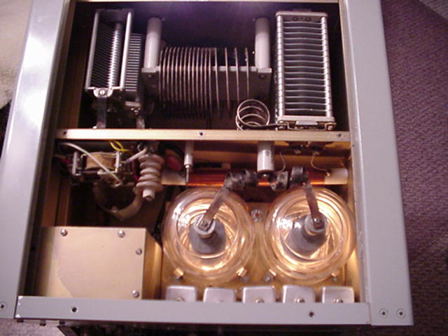
Henry 2K-4/3K-A
Note the flat-blade coil L adjustment screw on top of the five band coils
WARC Bands:
Most Henry RF amplifiers were manufactured before the WARC bands (30, 17 & 12 meters) were allocated to amateur's. So there are no tuned input circuits or band switch selection for these bands. However if you used the following chart and adjust the corresponding band tuned input L, you can get good drive and fairly low SWR for the WARC bands.
| WARC BAND | AMPLIFIER BAND |
| 30 Meters | 20 Meters |
| 17 Meters | 15 Meters |
| 12 Meters | 10 Meters |
Tuned Input Alignment Procedure:
The following RF amplifier turning procedure is only a recommendation. Follow it at your own risk. Reference your RF amplifier's owner's manual for their recommendations.
*** DANGER ***
RF Amplifiers Have Lethal HIGH VOLTAGE Inside
-
Power off both the transceiver and RF amplifier
-
Remove the amplifier covers to expose the input coils
-
Disable any RF amplifier HV or AC power interlocks
-
Connect the transceiver's RF output to a SWR meter input
-
Connect the SWR meter output to the RF amplifier's RF input
-
Place the SWR meter into reflected mode
-
Connect a LOAD to the RF amplifier's RF output
-
Connect the PTT line between the transceiver and RF amplifier
-
Power on the transceiver and RF amplifier
-
Set both the transceiver and RF amplifier to the same band
-
Set the transceiver VFO to the desired operating frequency
-
Key the transceiver and RF amplifier with approximately 30 watts RF drive
-
Adjust the RF amplifier TUNE and LOAD air variables PI output tank circuit for best RF output
-
Using an insulated long flat-blade screwdriver, while watching the SWR meter, adjust the L slug for the band you are on for minimal SWR
-
Un-key the transceiver and RF amplifier
-
Repeat steps 10 to 15 for each band
-
Power off the transceiver and RF amplifier
-
Enable all RF amplifier HV and AC interlocks
-
Install all removed cabinet covers
Alignment Troubleshooting:
Reference your vacuum tube data sheet for maximum Ig (Grid Current). When adjusting the input circuit, watch the Ig meter on the RF amplifier and DO NOT over drive the tube grid or you may damage it.
You may see changes on the input SWR when the PI network tank circuit is being adjusted. This is typical. What is happening, the internal tube Z characteristics change as the tube's output loading changes. The tube's internal Z capacitance under 10w drive will be different than the tube's internal Z capacitance input under 30w drive, and the internal Z capacitance will again be different when you drive with 100w drive. There is nothing you can do about this. It’s the laws of physics for vacuum tubes. What you need to do is find what sweet spot works best for you. In other words if you are going to drive the tube the majority of the time with 90w drive, load the output circuit to resonance with 90w drive, then tune the input circuit for the lowest SWR for that 90w power drive level. You need to find a compromise spot.
Don't expect a perfect 1:1 flat SWR on all bands. However you should be successful in achieving a reasonable minimal SWR between the transceiver and RF amplifier input. If not, the cause is most likely one of the following:
-
Bad tube, internal Z characteristic are way out of specification
-
Open or age capacitor that changed value in the input circuit
-
Open or shorted coil, or broken ferried slug in the input circuit
-
Open by-pass capacitor off one of the tube socket pins
Since band VFO frequency and drive power level will change the SWR input slightly, I like to use the internal ATU (Automatic Antenna Tuner) inside my transceiver when I have the transceiver connected to my Henry RF amplifier. This allows me to always have a 1:1 SWR between the transceiver output and the RF amplifier input. The ATU will adjust for any slight Z impedance miss-match.
As the tube ages it's internal tube Z characteristics will change and you may see the SWR become out of alignment between your transceiver output and amplifier input. Also if you change out the older tube with new tube, you may find the input SWR is now out of alignment. This is because the new tube's internal capacitance will be different then the older aged tube you replaced.
When using tubes in pairs, its best to use "matched" pairs. This means the internal Z characteristics are the same for both tubes. If one tube goes bad, its best to replace both tubes as a match Z pair.
One advantage of using a solid state output device over a vacuum tube, the solid state device's internal capacitance characteristics stays more constant with less variation over the life of the device, unless it shorts or open.
Conclusion:
Once the RF amplifier's input circuit is correctly tuned, you will have a happy transceiver looking into a nice 50 ohm Z impedance load, and maximum RF power output from your Henry amplifier. You will see the glass tubes with a nice reddish-orange glow to the plates and full RF power output.