NE7X - Phoenix Arizona USA
Henry 2K-4 & 3K-A RF Amplifiers
QSK Modification
Webpage Last Updated on: 07/29/2011
Henry RF Amplifier Information Center Web Site
Information about other Henry RF Amplifiers
Modifications & Upgrades
ISSUE:
My ICOM IC-7700 transceiver was showing high infinity SWR for approximately 25ms every time I keyed the transmitter, before it would go to 1:1. This happened only when the Henry Radio 2K-4 or 3K-A RF amplifiers were in-line.
Test your transceiver and RF amplifier:
Place a SWR meter between the RF output of your transceiver and your amplifier RF input. Place the SWR meter in reflected position and then key your transmitter with carrier output. The SWR reflected meter needle should not move, bounce or jump. It should be a solid steady ZERO reflected each time you key your transmitter. If there is any movement of the reflected needle when first keying your transmitter, you have an issue.
CAUSE:
When the IC-7700 PTT is keyed, RF output does not occur until after 6ms. This 6ms RF output delay it designed into the IC-7700 to allow any external T/R switching to complete before RF output. However the internal mechanical T/R relay in the Henry was taking ~31ms to fully energize and complete switching state. This caused the IC-7700 to transmit into an open circuit for ~25ms.
CONCERN:
Transmitting into an open circuit for ~25ms every time I pressed PTT could cause damage to the RF output transistors. This issue applies not only to the IC-7700, but to most modern transceivers.
ICOM's RESPONSE
:Checking with ICOM technical support, there are no user or factory hidden service menus for the IC-7700 to adjust or extend the 6ms RF output delay. This delay is a fixed static value. The IC-7700 also DOES NOT have a simple transmit logic inhibit input for closed loop. ICOM only supports propriety CI-V data closed loop.
SOLUTION:
To resolve this problem I decided to replace the slower mechanical T/R relay in the Henry with high speed Gigavac model GH1 and GH3 (datasheet) 5KW 6ms 12VDC SPDT vacuum relays. Not only will this resolve the issue of having the IC-7700 transmitting into an open circuit every time I key the transmitter, it will also allow the amplifier to run full QSK break-in. I found the GH1/GH3 vacuum relays actually switched in 3ms. The 6ms is the manufacture's worse case value.
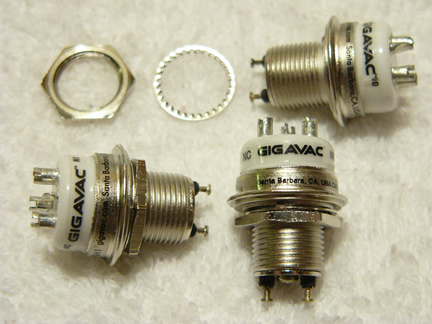
GH1-HAM
This modification requires three SPDT vacuum relays (two GH1 relays for RF and one GH3 relay for HV). One for switching the amplifiers antenna RF output, one for switching RF input, and one to remove the 3-500Z grid bias.
Since this modification utilizes three separate SPDT vacuum relays, the IC-7700 and the vacuum relays MUST all be switched in a certain sequence. Sequencing is required to prevent any RF damage from occurring to either the RF amplifier output circuit (3-500Z tubes), vacuum relay contacts (arcing and pitting) or the IC-7700 transceiver. The sequence is:
The IC-7700 PTT is keyed
- RF OUT vacuum relay in the Henry is switched
- RF IN vacuum relay in the Henry is switched
- BIAS vacuum relay in the Henry is switched
- IC-7700 RF output occurs
This sequence is equally important when un-keying from transmit, The IC-7700 must stop RF output first and the three vacuum relays must be un-energized in the reverse order as they were energized.
To accomplish sequencing for the vacuum relays, I added a JWM Engineering Group four step port programmable SEQ-QSK T/R Sequencer.
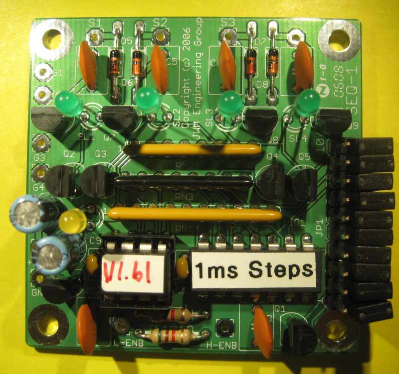
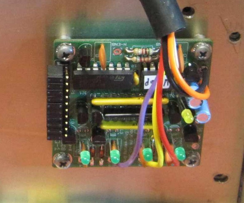
SEQ-QSK
SEQ-QSK Specifications
- 13.8 Vdc @ 50ma typical (no switched output active)
- 35 Vdc @ 600 millamperes open collector switching capability, Four outputs total
- Enable High or Enable Low input to activate sequencer
- Visual states displayed on 4 Green State LED's
- 1 second Yellow Heartbeat indicator
- Programmable delay times from 1 ms to 32 ms (default is 15 ms)
- Operating Temperature Range 0 Deg C to +70 Deg C
MODIFICATION:
The following modification describes a step-by-step procedure to perform the QSK mod to a Henry 2K-4. However the Henry 3K-A is the exact same procedure. The only difference between the Henry 2K-4 and 3K-A, the 3K-A has a higher plate voltage power supply. Both Henry amplifiers have identical chassis and wiring.
This QSK modification is very easy since the original mechanical T/R relay is located on the top chassis RF deck. All that is required is to remove the cabinet top cover and the inter-top RF shield cover. No modification to the power supply is required, since the original T/R relay runs on 12VDC, and so does the Gigavac GH1/GH3 vacuum relays and SEQ-QSK sequencer.
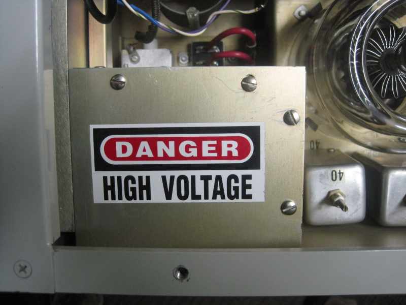
*** DANGER ***
RF Power Amplifiers Have Lethal High Voltages
Remove AC power , antenna and all transceiver interconnect cables. Remove the top outside cover (4 screws) and then remove the inside RF deck shield cover (9 screws).
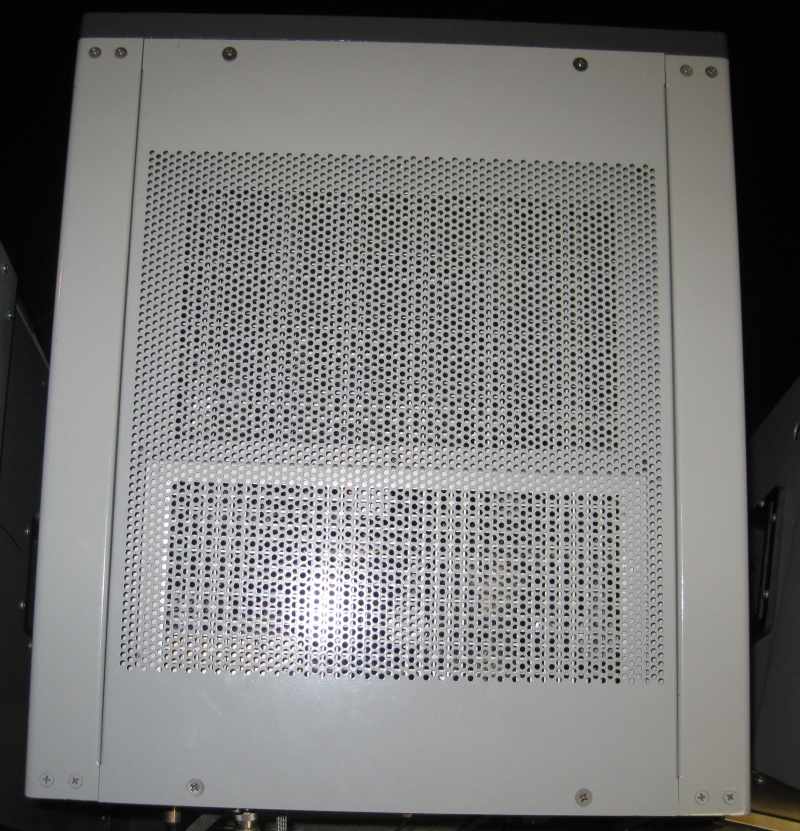
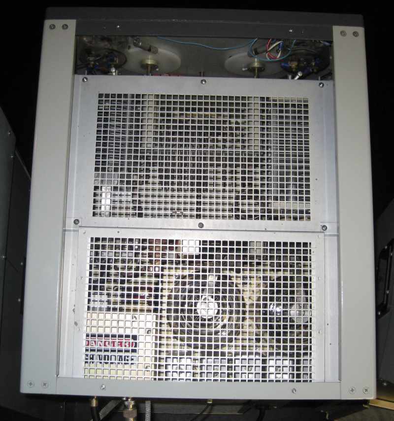
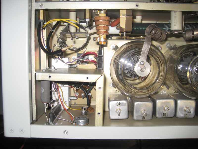
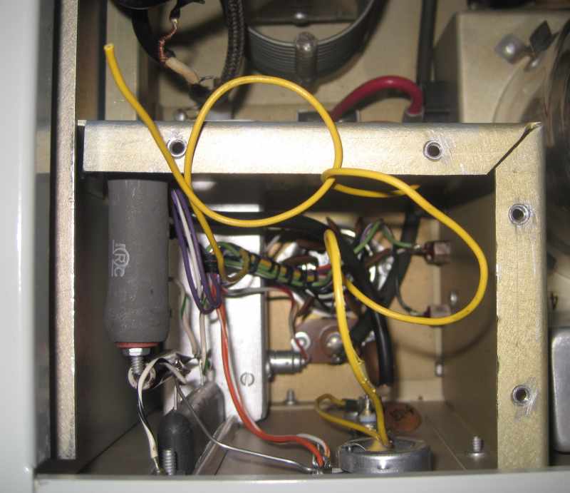
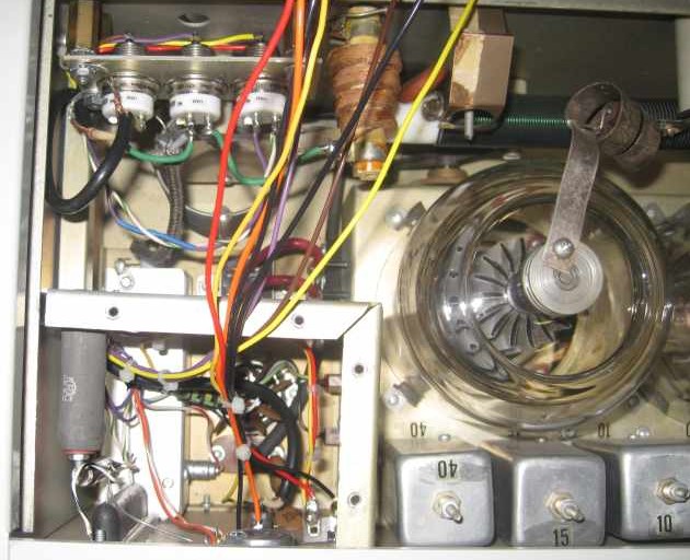
Here is the Henry 2K-4 with top covers removed, looking from rear, the T/R relay is along the left side of the top chassis just above the RF out SWR compartment.
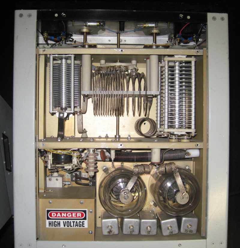
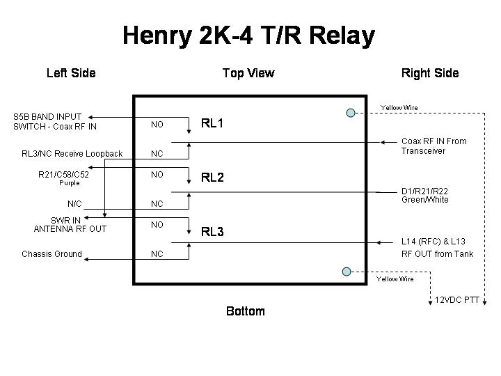
Original Mechanical T/R Wiring
Reference the Henry 2K-4 Service Manual and Schematic for Additional Information
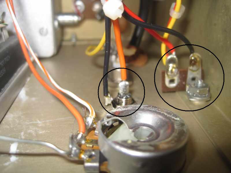
Close up view of the Original Mechanical T/R 12VDC Relay
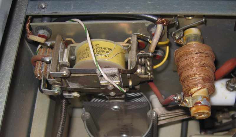
The T/R relay "assembly" is easy to remove. There are four flat head screws/lock-washers/nuts with 1/2 inch spacers holding the "relay plate" to the chassis. Easy access to the screw heads from the RF tank output section of the chassis. There is also one screw/nut holding the RFC ground and coax shield braid ground lugs to chassis. The hardest part of removing the "relay assembly" is not dropping the nuts or washers into the chassis. Its your choice, you can either cut the wires off the mechanical T/R relay, or unsolder them. I chose to unsolder the coax leads and cut the wires.
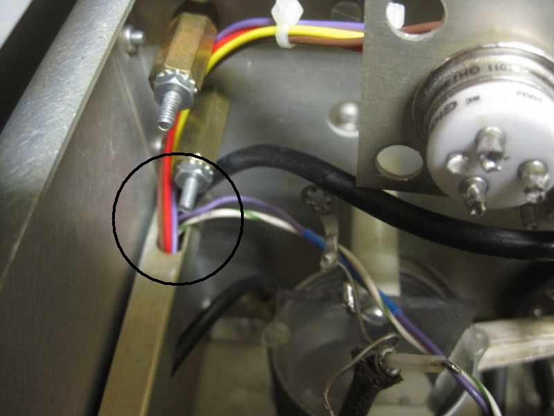
Here is the mechanical T/R "relay assembly" after it has been removed
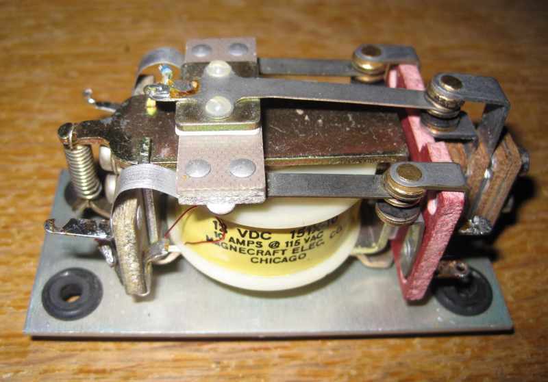
Note the two yellow wires. These are the 12VDC PTT wires. They are coming from the square metal wire-way along the left side of the chassis. More on these yellow wires later.
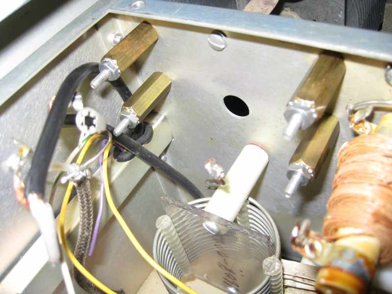
Chassis with mechanical T/R "relay assembly" removed
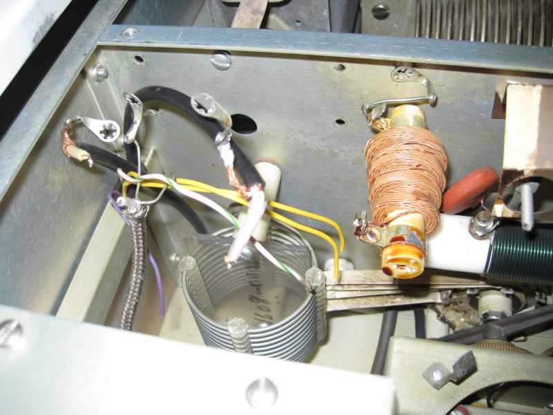
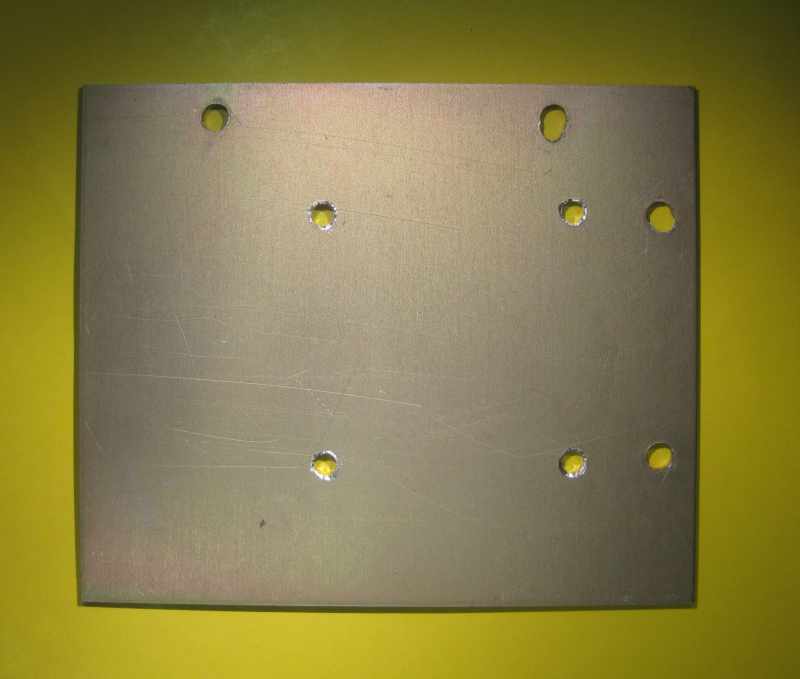
Remove the relay and all the rubber grommets off the relay mounting plate. This plate will be reused to mount the three vacuum relays. (see "Modification Options" section of this document for rubber grommet information)
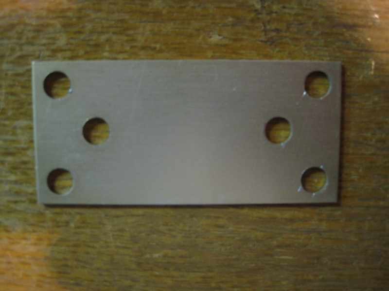
Here is what the relay plate looks like after everything has been removed.
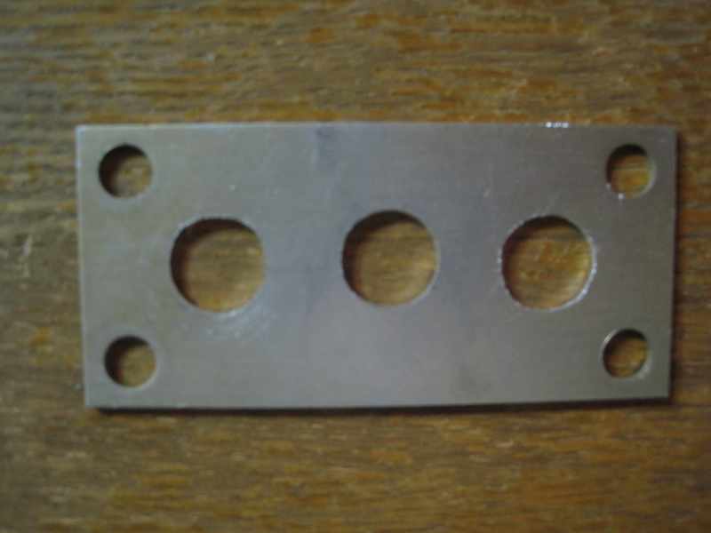
Drill/Punch out three 18mm (≈0.709") holes. I used a 5/8 inch Greenlee chassis punch, then a round rat tail file to enlarge the three holes.
Mount the three vacuum relays to the plate. Make sure you have the pins orientated as shown in the below picture. This will allow for best wiring.
GH1 (RF IN) GH1 (RF OUT) GH3 (BIAS)
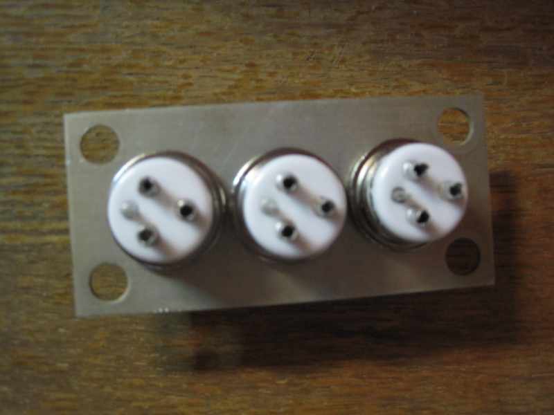
GH1 (RF IN) GH1 (RF OUT) GH3 (BIAS)
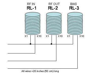
Referencing the following diagram, wire the three vacuum relay 12V coils, so the three X1 coil pins are tied together, and each of the X10 coil pins have their own separate wire. When done, you should have a total of four ~20 inch (50 cm) long wires coming from the relay assembly.
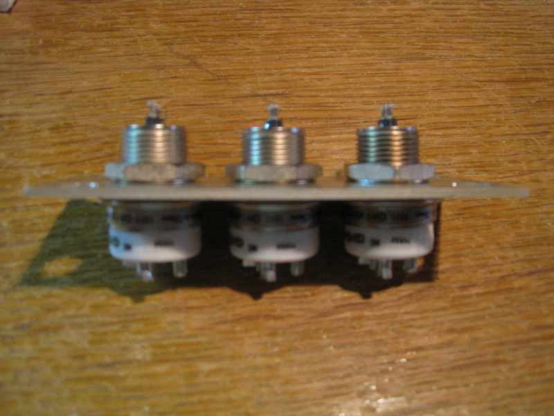
The following picture is an example on how the vacuum relay coil wiring should now look.
GH1 (RF IN) GH1 (RF OUT) GH3 (BIAS)
You need to come up with some 1 inch (2.5cm) long spacers or mounts. These are required to insure there is clearance between the vacuum relay coil pins and the chassis. Install the spacers into the four original holes where the T/R relay plate was removed.
Remove the top cover of the SWR compartment, looking from the rear, this is the cover with the four screws, left bottom
Looking inside the SWR compartment you will see the two yellow 12VDC relay wires in the wire harness. One yellow wire going to the octal plug on the bottom of the chassis (+12VDC internal power supply) and one yellow wire going to the "RELAY CONTROL" (PTT) RCA plug on the rear chassis panel.
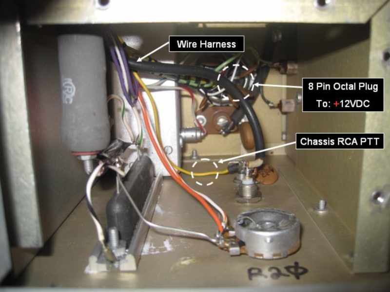
Using a needle nose pliers, "gently" pull the two yellow wires out of the harness and metal wire-way so both wires ends are now inside the SWR compartment.
Identify/Label which yellow wire goes to the octal plug +12VDC internal power supply and which yellow wire goes to the "RELAY CONTROL" (PTT) RCA plug on the rear of the chassis.
Route the four new wires coming from the relay assembly into the metal wire-way hole along the left side of the chassis until the four wire ends come out inside the SWR compartment. It maybe a little tight, however with a little persistence, there is enough room and the wires will go through.
Mount the relay assembly to the four stand-off studs, inserting the three coax shield ground lugs behind the mounting nuts. Make sure these coax ground lugs are making good chassis ground contact.
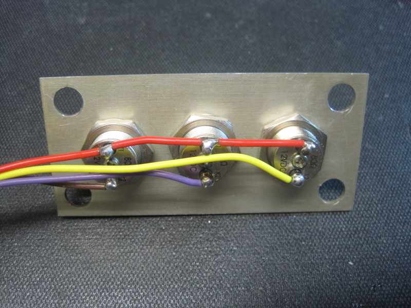
Once the relay assembly is securely mounted, using a 200-250W soldering iron/gun, solder the RF IN, RF OUT and BIAS wires to the vacuum relays pins. You will need to add two jumpers and extend/lengthen the purple wire by about 3 inches (8cm).
Reference the original mechanical T/R wiring diagram shown at the beginning of this modification, or the Henry 2K-4 schematic for correct relay wiring information.
LEFT RELAY (GH1) = RF IN CENTER RELAY (GH1) = RF OUT RIGHT RELAY (GH3)= BIAS
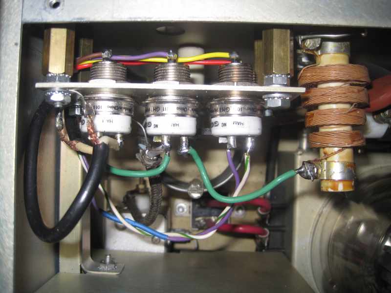
The Above picture is how the relay assembly should now look. Double check your wiring.
Wiring errors may result in damage to the RF amplifier, or worse, to your transceiver.
================================================================================
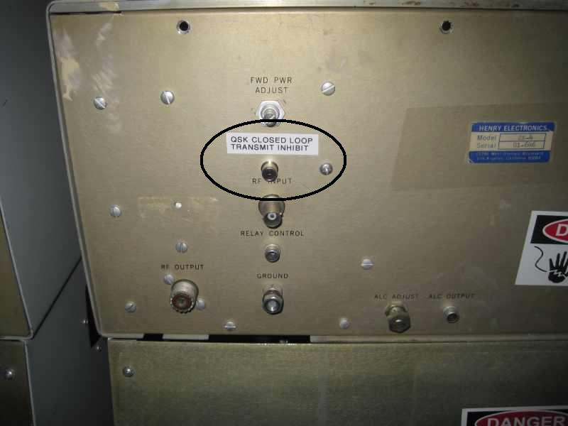
Install a RCA plug for the "Closed Loop" connection. Drill a 1/4 inch (6mm) hole into the rear of the amplifier cabinet between the "RF INPUT" BNC connector and the "FWD PWR ADJUST" meter potentiometer.
Mount 1/4 inch (6mm) RCA chassis plug into this hole, including a ground lug around the plug under the mounting nut. This RCA plug will be used for the optional "QSK CLOSED LOOP TRANSMIT INHIBIT" connection to the transceiver.
Add a 12 inch (30cm) long wire to the center pin of the transmitter inhibit RCA plug, along with a 12 inch (30cm) long wire to the RCA plug ground lug.
Install an insulated terminal strip stand-off to one of the two inside SWR compartment cover mouthing screws. (see the next picture)
Connect the following three wires to this insulated stand-off lug:
The +12VDC yellow power supply wire coming from the chassis octal plug at the bottom of the SWR compartment
The wire coming from the three vacuum relays pins X1
Add a new 12 inch (30cm) long wire. This will connected to the SEQ-1 for +12VDC power
If the terminal strip you installed has a ground lug, add a 12 inch (30cm) long wire to it for a second ground.
You should now have a total of eight (8) wires, approximately 8-12 inches (20-30cm) long each, coming out of the SWR compartment. These wires will be connected to the SEQ-QSK sequencer.
Three (3) wires coming from the vacuum relays (one from each relay X10 pin)
Two (2) wires coming from +12VDC power terminal strip (+12V and GND)
One (1) wire coming from RELAY CONTROL (PTT) RCA plug on chassis rear (center pin)
Two (2) wires coming from new transceiver inhibit RCA plug on chassis rear (center pin and GND)
Trim the length of all eight (8) wires so they extend approximately three (3) inches (8cm)outside the SWR compartment.
Using an external 12VDC workbench power supply, follow the instructions in the SEQ-QSK user manual and program the SEQ-QSK for 1ms step speed. After you complete the modification, you may need to play with the sequence step speed to find the best step speed that works for your transceiver and environment. What I found:
1ms steps = ICOM IC-7700 (Complex CI-V packet data closed loop) SEQ-QSK not supported
2ms steps = Yaesu FT-2000 (Simple logic low closed loop) SEQ-QSK supported
1ms steps = Tentec Orion-II (Simple logic high closed loop) SEQ-QSK supported
NOTE: See Closed Loop information under "Modification Options" section of this document.
When identifying the best sequence timing, the two things to consider:
1:1 SWR between transceiver and amplifier input every time you key
No missing first "dit" on CW
======================================================
Looking at the SWR compartment top cover/lid, you will see it has four mounting screw holes. Looking from the rear, there are two holes along the top and two holes long the right side. The SEQ-QSK will be mounted inside the SWR compartment, to the top cover on the underside of this cover/lid.
Place/hold the SEQ-QSK to the underside and identify a mounting location. The location needs to clear the SWR compartment side walls/lips and the large resistors along the left side. Once a location has been identified, mark the four mounting hole locations with a maker, then drill four 11/64 inch (.4 cm) holes into the top cover/lid. The SEQ-QSK PCB is exactly 2x2 inch (5.1x5.1cm) square.
At this time you can mount an optional TVS (transient voltage suppressor) diode across the +12VDC input on the SEQ-QSK. The TVS will provide very fast responding when handling transient power spikes up to 1500 watt power. Considering the arc is a very fast and short duration phenomena, a TVS could possible prevent a failure of the SEQ-QSK.
http://Mouser.com sells them for $0.59 each in single qty. They break down at around 18 volts which would be a good voltage to stop any over-voltage. The regulator on the SEQ-QSK is rated at 30 volts maximum input, so 18 would be a good level.
The Mouser part number is: 863-1.5KE18AG
Mount the TVS directly on the SEQ-QSK board by soldering the cathode lead into the +12 volt hole and the anode lead to the closest ground hole. It is important to keep the leads of the TVS as short as possible as the inductance of the lead length can cause an overshoot. And the overshoot is what you want to suppress, not make worse. Leave enough TVS lead from the +12 volt hole to allow you to attach the +12 volt line to it.
Now attach the eight (8) wires coming out of the SWR compartment to the SEQ-QSK. Strip the insulation off the tips of each wire, then insert the wires into the correct hole on the SEQ-QSK as per the following diagram. Solder each wire to the SEQ-QSK foil side.
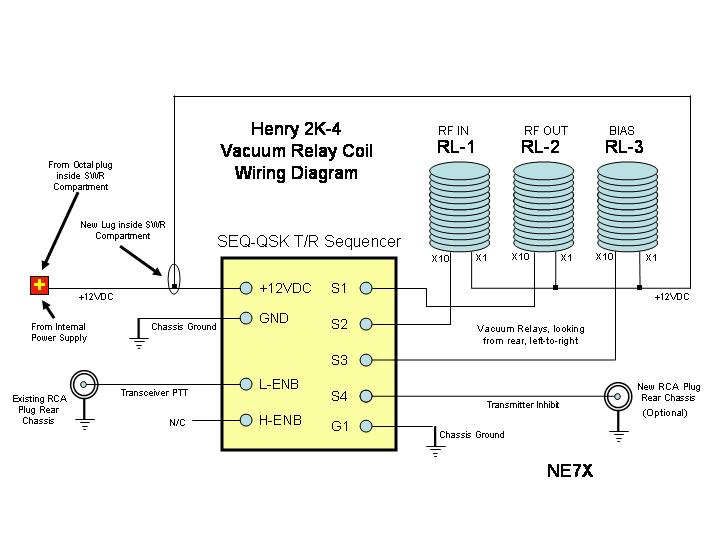
SEQ-QSK Vacuum Relays
Using four 4-40 machine screws/nuts with 1/4 inch (6.35cm) spaces, mount the SEQ-QSK to the inside/underside of the SWR compartment top cover. Use plastic cable ties or plastic/rubber sheathing to create a wire-harness of the eight wires.
Install the SWR compartment top cover. Route the SEQ-QSK wire-harness so it does not push up against the high wattage resistors along the left side of the SWR compartment. Using four screws, tighten and secure the cover.
------------------------------------------------------------------------------------------------------------
For the ICOM radios (IC-7600, IC-7700 & IC-7800) there are two different output types to key an external amplifier, RELAY and MOS-FET. The RELAY is mechanical and a few ms slower then the MOS-FET. The SEQ-QSK sequencer only draws a few milliamps, so to obtain the fastest switching speed, and to prevent any false amplifier keying due to relay bounce, under the "ACC Set Mode" menu, set the LEAD menu to: "SEND RELAY TYPE = MOS-FET.
That's it! The
modification is complete.
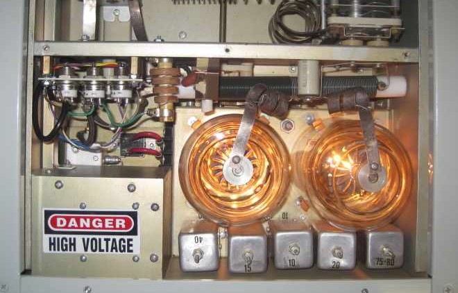
Don't you just love the warm
orange
glow of those 3-500Z tubes
!!!
FINAL ASSEMBLY:
Install the top inside RF chassis cover (9 screws) and then install the top cabinet outer cover (4 screws). This completes the modification. Connect up transceiver interconnect cables, antenna and apply AC power.
==========================================
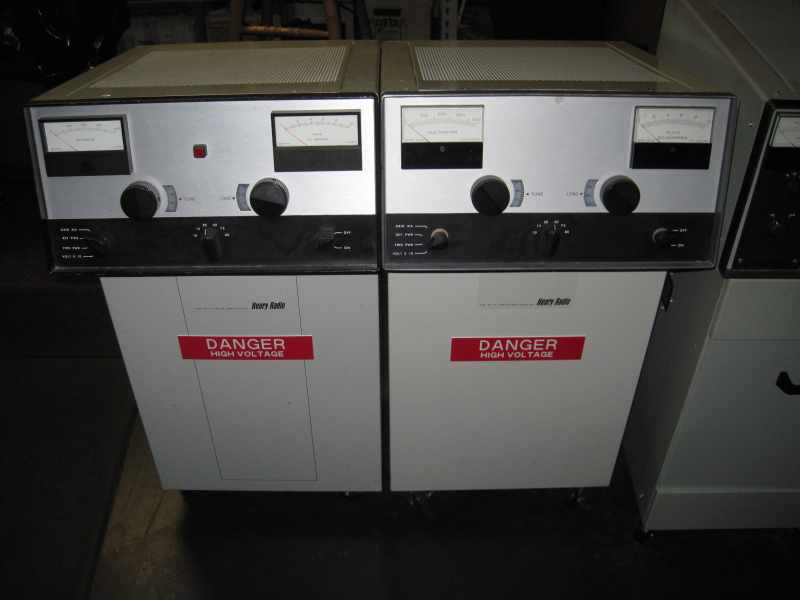
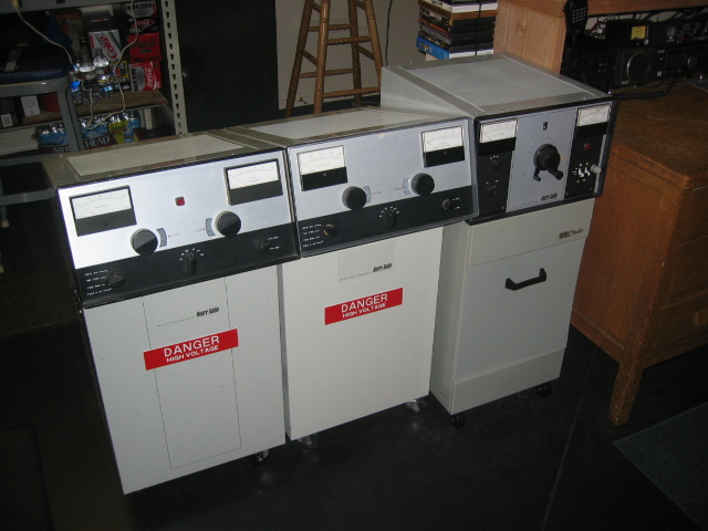
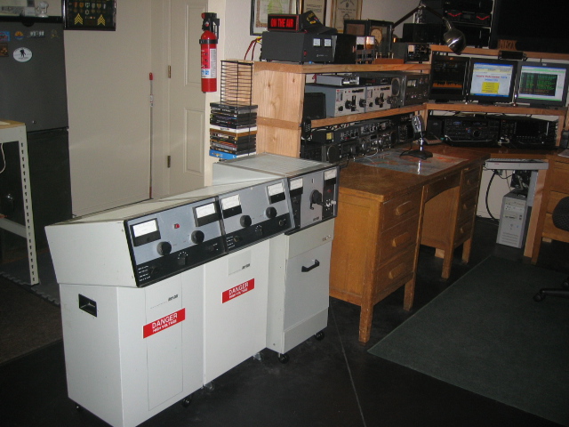
MY HENRYS
Here are my two Henry 2K-4s in their operating position, along side a Henry 2DK-5. This QSK modification has been successfully applied to all three Henry amplifiers. The other Henry 2K-4 is connected to my Yaesu FT-2000 and the Henry 2DK-5 is connected to my Tentec Orion-II.
Now when I operate my IC-7700 with the Henry 2K-4 I get a perfect 1:1 SWR every time I key the transmitter, even when I run the IC-7700 in F-BKIN (Fast Break-In) CW. I do not loose the first "dit" when sending CW.
MODIFICATION OPTIONS:
Vibration
You can add four rubber grommets on the relay mounting plate screw holes to isolate the plate from mechanical vibrations to the chassis. This will reduce/subdue the relay "clicking" sound. However if you do this, you need to make sure all the coax shields and other wiring have proper chassis grounding. Another possible solution would be to enlarge the vacuum relay mounting holes, then inserted large rubber grommets with an ID the same as the OD of the vacuum relays. You can then insert and mount the vacuum relays inside the large rubber grommets.
Relays
If you want to save some $$$$, you can replace the GH3 HV vacuum relay which switches the BIAS to a less expensive high speed micro reed relay. The reed relays cost about $5-10 each. You might also replace the RF input relay with the same reed relay to save even more $$$. If you go this way, make sure the reed relays will handle the BIAS current and 200 watts of RF drive. By doing this, you will only need one of the GH1 5KW RF vacuum relays to switch the high RF output. If you decide to use reed relays, just make sure the reed relays are 12VDC and have the same microsecond switching speed as the GH1 (6 ms).
You can also use Jennings RJ1A-S26 vacuum relays. These are 26VDC relays and relativity available on eBAY for a modest priced. Most are surplus used, so make sure you check the history before purchase. You will need to add a 26VDC power supply to the lower power supply deck of the 2K-4. The power supply will consist of a 120VAC-to-24/26 VAC 1 amp transformer (Radio Shack PX-24C1 or equivalent), one 1N4001 diode and one 50uf 100V electrolyte filter cap. Make sure you wire the primary side of the transformer to a 120VAC source, not 240VAC. DC connection to the vacuum relay coils can be made by disconnecting the 12VDC line at plug P1-pin4, and insert the 26VDC to the yellow wire feeding the relays. Consult the 2K-4 schematic for wiring details.
When selecting vacuum relays you should be aware there is a difference between HV and RF type vacuum relays. The RF relays allow switching of RF voltages and the HV relays do not. If you use the HV type for RF switching, they will work, however you will burn/arc/pit the contacts over a short period of time.
A second source for Gigavac vacuum relays is MGS (MAX GAIN SYSTEMS) in Marietta, GA.
Closed Loop
Closed Loop means the transmitter will inhibit putting any RF output until it receives a signal from the sequencer indicating all three of the RF amplifier vacuum relays are in the proper state. The fourth logic output step {S4} of the SEQ-QSK can be used for this. ICOM radios do not support simple logic closed Loop inhibit, however Yaesu and Tentec transceivers do. Consult your Yaesu and Tentec owner manuals for more information.
FINAL NOTE:
This vacuum T/R relay modification can be applied to any of the older RF amplifiers which use slow mechanical T/R relays, it does not apply only to Henry 2K-4s. If you are using an older RF amplifier, I highly recommend you check and validate the SWR between your transceiver output and amplifier input. Make sure it is not going to infinity for a few microseconds when you first key your transceiver. If it is, STOP! before any damage to your transmitter RF outputs occurs.
Henry RF Amplifier Information Center Web Site
Additional Information about other Henry RF Amplifiers
Modifications & Upgrades
Happy QSKing