RF Amplifier
External QSK Interface
Model: QSK-2KW
By: NE7X - 05/23/2011
Description Overview:
The QSK-2KW is an external RF T/R interface device which connects to any RF vacuum tube amplifier. It provides full high speed RF amplifier T/R switching for CW or digital break-in operation. The QSK-2KW requires a low current keying input, so it can be directly keyed by your transceiver without requiring a separate external interface buffer device.
The QSK-2KW interface uses high speed Gigavac model GH1 and GH3 (datasheet) "5KW" SPDT 12VDC vacuum relays to provide lightening fast T/R switching. The relay contacts of the GH serials vacuum relays will easily handle the RF power output of legal limit RF amplifiers. Kilovac HC1 and HC3 vacuum relays can also be used.
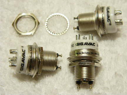
Two GH1 (RF) and One GH3 (HV-BIAS)
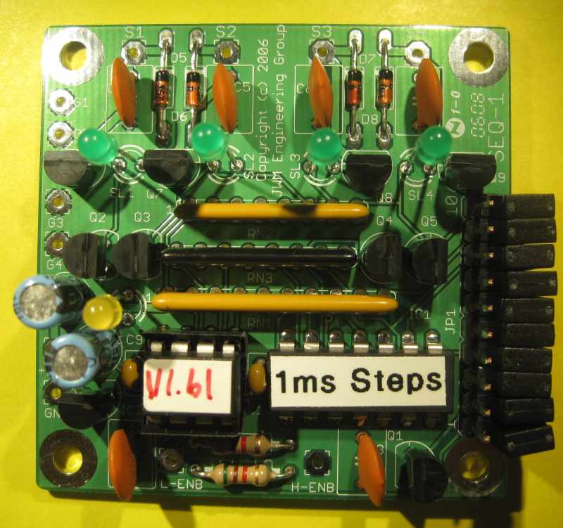
Sequencing of the vacuum relays if very important to insure the RF amplifier is not in the conductive state before the RF output and input circuits have switched states. To accomplish sequencing for the vacuum relays, the QSK-2KW uses a low current JWM Engineering Group four step port programmable SEQ-QSK T/R Sequencer.
SEQ-QSK Sequencer by: JWM Engineering
Installation Requirement:
The QSK-2KW installation does require a minimal modification to the RF amplifier for BIAS switching. This is less invasive then a full removal and replacement of the slower mechanical TR relay. By utilizing a 1/4 (or 1/8) inch stereo "switched" jack, when the QSK-2KW is disconnected from the amplifier, the amplifier is returned to full original normal usage. This RF amplifier modification requirement is the same for connecting an Ameritron QSK-5 or Array Solutions QSK-MASTER external QSK T/R switch.

QSK-2KW Rear Connections:
INHIBIT = Output (RCA) - Logic Low - The transceiver will not put any RF output until logic low appears. This is an optional connection. Consult your transceiver owner's manual for additional closed loop inhibit information.
AMP KEY = Output (RCA) - Logic low - Switches the RF amplifier's mechanical TR relay so input and output circuits are enabled.
XMIT KEY = Input (RCA) - Logic low - From the transceiver to key the RF amplifier.
AMP BIAS = Output (Stereo 1/4 [or 1/8] inch phono jack, normally closed switched) - BIAS voltage switching for placing the RF amplifier into transmit mode.
TO AMP IN = Input (SO239) - To amplifier RF input coax connector.
FROM AMP OUT = Input (SO239) - From amplifier RF output coax connector.
XMITTER = Input (SO239) - From transceiver RF antenna coax connector.
ANTENNA = Output (SO239) - Connect to Antenna.
+12VDC = Input (2.5mm) - Approx 500ma minimal. Find yourself an old junk-box wall-wart.
GROUND = (Screw) Connected a wire jumper to both RF amplifier and Transceiver chasses.

QSK-2KW Schematic
Great Weekend Project:
If you decide to build one, here are some construction tips to help you with the project.
A 12VDC "Amplifier Enable Safety" relay is added to insure the RF amplifier is not mistakenly enabled into transmit mode without the vacuum relays being enabled. Adding this relay also supports keying RF amplifiers up to 125VDC. No additional transceiver buffer interface is required for RF amplifiers which use higher voltage TR relays, like Henry and Alpha which use 26VDC relays, or Heathkit and Collins which use 120VDC relays.
Ferrite chokes are added to all logic I/O connections to prevent false key ups.

QSK-2KW - Inside
Placement of vacuum relays should be as close as possible to the four SO239 coax connectors on the rear panel. This will reduce the wire lengths between the vacuum relay contact pins and the SO239 connectors, and help minimize any impendence SWR bumps at higher frequencies.
Make sure you use RF switching vacuum relays (Gigavac GH1) for the S1 "RF OUT" and S2 "RF IN", and a HV switching vacuum relay (Gigavac GH3) for S3 "BIAS." This will insure the vacuum relay contacts will not arc, pit or weld closed over years of usage. Also sequence timing for the vacuum relays is important so you don't "hot switch" the relays (SEQ-QSK).
The Gigavac vacuum relays can be substituted with Kilovac HC1 and HC3 vacuum relays.
Vacuum relays with 26VDC coils can be substituted. In doing so, the 12VDC power supply needs to replaced with a 24-26VDC external power supply, and a LM7812 voltage regulator needs to be added in series with the SEQ-QSK 12VDC power input and the "Amplifier Enable Safety Relay" coil. The SEQ-QSK S1-S4 outputs can switch up to 32VDC at 600MA each and can directly driver the 26VDC relay coils . For additional information about using 26VDC vacuum relays, reference the website: QSK Mod for Henry 2K

The vacuum relay mounting bracket is mounted on rubber grommets. This helps reduce chassis vibration and audible amplification when the vacuum relays are keying and un-keying. Add a flexible ground wire between the vacuum relay mounting bracket and chassis ground.

*** DANGER ***
There are lethal High Voltages inside RF amplifiers. Make sure the amplifier is disconnected from all power sources before making any modification.
RF Amplifier Modification:
Drill a hole in the rear of the RF amplifier chassis and mount a 1/4 inch (or 1/8 inch) Stereo "normally closed switched" jack. Cut open the RF amplifier's BIAS line which is in series with the mechanical TR relay contacts. Wire the two HOT pins of the stereo jack in series where you opened the BIAS line. The switched stereo jack will allow the circuit to be closed when the plug is removed. This places the RF amplifier back to normal original configuration when the QSK-2KW is not connected. No other modification is required to the RF amplifier. Consult your RF amplifier schematic for wiring information.

1/4 inch stereo chassis Jack
Note the five (5) wire lugs and the shorting contacts for each of the two HOT contact springs
DO NOT connect the BIAS wires to the ground lug
BIAS must be insulated off chassis ground
A 1/8 inch stereo switched chassis jack can be substituted

Wiring interconnect diagram between: QSK-2KW, RF Amplifier and Transceiver
Theory Of Operation:
If your RF amplifier has a "Stand-By/Operate" switch, place the switch into the Operate position.
When the QSK-2KW "Amplifier Enable" switch is turned on (enabled), the "AMP KEY" of the QSK-2KW goes logic low and energizes the RF amplifier's TR relay. This places the amplifier's internal RF input coax connector path to the input circuit and RF output coax connector to the output tank circuit. Since the BIAS circuit is open via the QSK-2KW S3 vacuum relay, the amplifier does not go into transmit mode. The receive antenna path is from the SEQ-QSK S1 to S2 normally closed vacuum relay contacts, then to the transceiver.
When a logic low from the transceiver is present at "XMIT KEY", this enables the SEQ-QSK and sequence begins for the three vacuum relays. First S1 output switches the antenna vacuum relay "RF OUT" so the antenna is now connected to RF amplifier output, second S2 output switches the vacuum relay "RF IN" so the transceiver out is now connected to RF amplifier input, and third S3 output switches on the BIAS vacuum relay, keying the amplifier. When logic low is removed from "XMIT KEY", the reverse occurs. S3 switches off the BIAS, S2 switches the RF IN, and S1 switches the RF OUT. The SEQ-QSK sequence speed can be programmed in 1 to 32ms steps. SEQ-QSK programming step speeds will depending upon your configuration and CW operating speed.
SEQ-QSK S4 output can be used for transmit loop-back inhibit. A transceiver will not put any RF output until it sees a logic low from S4. This insures all vacuum TR relays have fully switched state before the transceiver puts any RF output. Consult your transceivers owners manual for more details on utilizing this optional configuration.
SEQ-QSK Programming
Power off the QSK-2KW
Remove the cabinet cover
Add jumpers to pins 1<=>6 as described in the SEQ-QSK programming manual
Power on the QSK-2KW, wait 10 seconds
Power off the QSK-2KW
Remove ALL jumpers from the SEQ-QSK
Replace cabinet cover
Henry RF Amplifier Information Center Web Site
Additional Information about other Henry RF Amplifiers
Modifications & Upgrades
Happy QSKing
NE7X Web Site